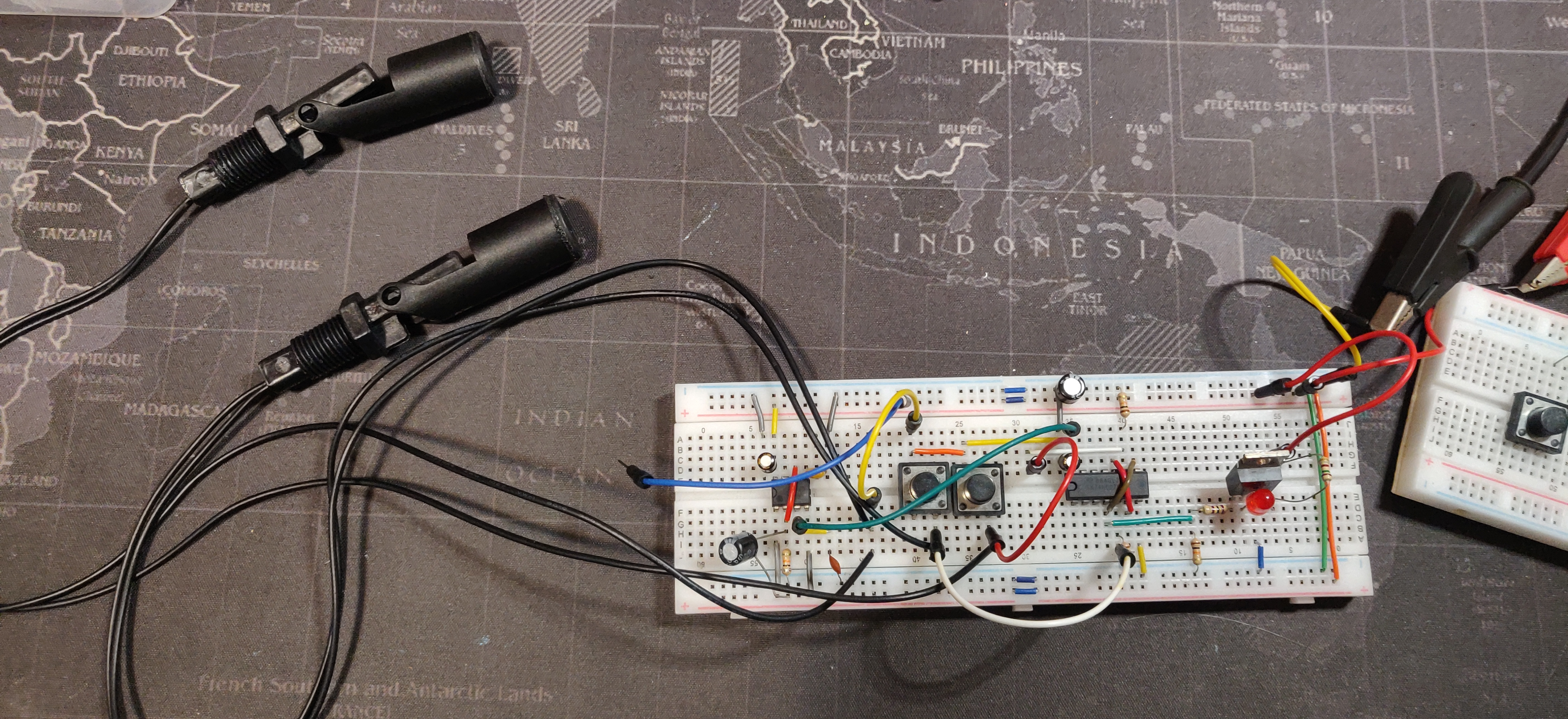
Water Pump Controller
September 2023

Introduction
Off and on, I work for a retired Polish man down the road from me. He's an interesting fellow. Anyway, a while ago he had a bore drilled on his property and installed a water pump and water tank. However, the tank overflows when he forgets to turn off the pump. I will now automate the process for him.
Features and Considerations
The table below contains the features and their respective considerations:
| Feature | Considerations |
|---|---|
| Main cutoff switch | Switches off both the pump and controller. |
| Delayed triggering of pump at main switch turn on/off | A rudimentary timing circuit or a second "soft" switch. |
| Automatic and manual control | Circuitry is required to monitor the water level of the tank and start filling when the water level is at the defined "low" level. Momentary switches are needed for manual control. |
Schematic Design
A solid state relay (SSR) is used to handle the large current draw of the bore pump. The bore pump has the following specifications:
| Brand | Grundfos |
| Model | 98699156 |
| Rated power | 1.1 kW |
| Rated voltage | 240 VAC @ 50Hz |
| Rated current | 7.1 A |
| Starting current | 480% (34.08 A) |
Therefore, I need an SSR with a minimum current rating of 40 A at 240 VAC. The KSI240D40-L SSR sold by JayCar is used. According to its datasheet, it has a minimum turn-on voltage of 4 VDC, and a maximum input current of 25 mA (both suitable values for pairing with low-power digital electronics). The SSR has an snubber built into it. A snubber is the AC-equivalent of a flyback diode used in DC inductive load applications to attenuate back-EMF.
How does one control the switcing on and off of the pump? One float switch could be used, but would result in frequent triggering of the pump and could cause premature wear. The next option is to use two float switches. If there is no water at the top switch, don't turn on the pump until water falls below the bottom switch. Once water falls below the bottom switch, turn on the pump, and then turn off the pump only once water reaches the top switch again. This logic requires some kind of state memory. A SET-RESET latch (SR latch) can be used in this scenario, as it holds one bit of infromation in memory. Namely, the top switch will reset the latch (turn off the pump) and the bottom switch will set the latch (turn on the pump). In this design, the Texas Instruments SN74HC02N quad dual-input NOR gate DIP IC is used. According to its datasheet, SN74HC02N can source or sink 200mA, which provides plenty of overhead when powering the SSR (25 mA) and power-indicator LED (20 mA).
How does one prevent arcing inside the main switch in the event that the water level is low enough to trigger filling? The answer is a delay or "soft" switch. Initially, this delay was implemented on breadbord using an NE555 timer, as it has a comparator circuit inside. However, a second "soft" switch was used in the final design as it was simpler. The drawback is that arcing in the main switch may sometimes occur if the operator forgets to flick the switches in the correct order. I don't envisage the controller having to be frequently switched on/off, though, so this shouldn't be an issue.